Lulzbot Mini / Prusa Mini Hybrid: Update #2: Marlin Updates, Novel Bed Mount, Octoprint, PrusaSlicer and Ultimaker Cura.

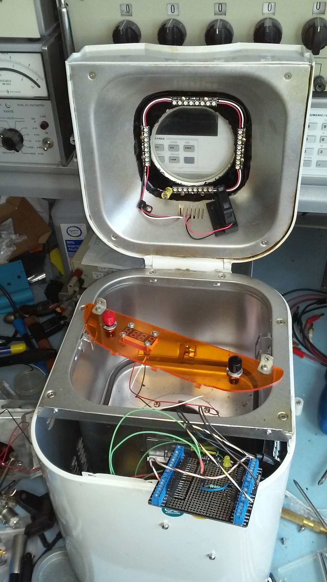
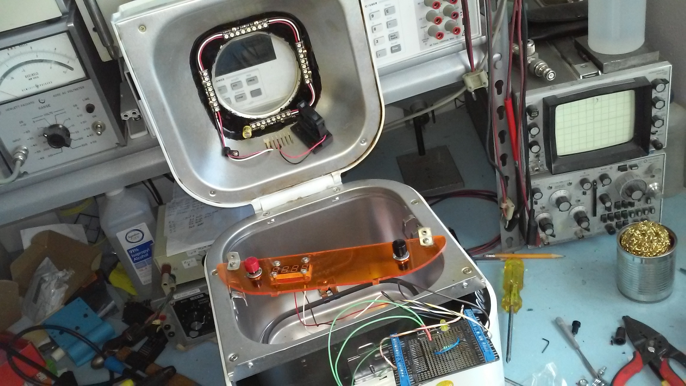
So it has been awhile since I worked on this project, but I am happy to report that after a few weeks of minor frustration with marlin hiccups I have now started to make big progress again.

First test prints with Lulzbot mini / Prusa Mini Hybrid Mod. Print is obviously not centered on the new bed but my z-axis did not crash!

My top objectives are:

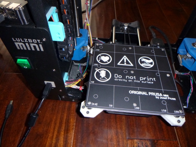
1. To get a Lulzbot Mini 1 modded (with minimal effort) to have a Prusa Mini removable bed plate system. Done!

2. To continue to use the original stock Rambo Mini 1.1b electronics board, but with a new up-to-date (custom) marlin firmware. Done!

3. To be able to print like I did before with everything centered and adjusted to the correct height for printing on the new removable print bed. And to be able to print with the old Lulzbot Cura 21.08 or the newer PrusaSlicer. Done-ish, but needs tweaking!

Other future modifications may be: An upgrade to a newer Rambo Einsy with trinamic stepper drivers for ultra quiet use. Possible z-axis modifications to be more like a Lulzbot Mini 2. A new extruder design with possible automatic bed leveling sensor pinda probe. Add an LCD screen!

I was testing with the marlin 2.0 bugfix branch

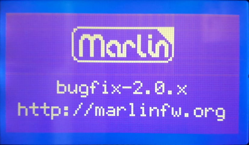
The first major hurdle lately has been trying to update to Marlin 1.9 or Marlin 2.0 with the configuration settings to work correctly with the Lulzbot Mini. I got pretty far along when i decided i wanted to center my new prusa mini bed plate when a print begins.

I ran into a weird Marlin bug where the manual_y_home_pos setting would invert the y-axis stepper motor and crash the machine! I tried reporting the bug to the marlin code people, but no one would help. They just kept asking the same annoying question over and over whether I was testing with the bug fix branch, which i replied multiple times that i was.

https://github.com/MarlinFirmware/Marlin/issues/18479

The “fix” for this came from a helpful tip from my friend who suggested i use the “Drunken Octopus” Marlin fork which was originally being maintained by lulzbot before the awful situation where they nearly went bankrupt, fired over 100+ employees illegally, and eventually got bought out and moved to North Dakota. It worked, so I’m thinking it must come down to some overlooked configuration setting I must have missed??

https://github.com/drunken-octopus/drunken-octopus-marlin

The Drunken Octopus fork is now maintained for lulzbot-type machines by that same former employee and is now also used for the new SynDaver Axi Desktop Printer which is a 70-80% clone of the Lulzbot Taz 6 / Pro series. The SynDaver Axi printer is not entirely open source being a hybrid of open source and proprietary, which is an interesting mix, but I don’t necessarily have a problem with that as long as the original source is available (which is).

https://github.com/SynDaverCO

In an ideal world I do think some licences like the new CERN-OHL-S Licence are what open source hardware and software should aspire to be. Basically the idea that if you use open source that the whole product from then on and forever will be open source. That would mean no mixing of open source and proprietary. But we do not live in an ideal world (yet). I personally think creative commons licences with non-commercial, no-derivatives, and other restrictive licences are insulting and are NOT true open source. I personally do not honor them because of their inherit hypocrisy. If you want to share your work with the world then do so in it’s entirety or don’t do so at all. I’m not the only one with this opinion, in fact the OSHWA says so as well.

Why aren’t non-commercial restrictions compatible with open source hardware?

There are a few reasons. If you place a non-commercial restriction on your hardware design, other people don’t have the same freedom to use the design in the ways that you can. That means, for example, that if you and someone else both release designs with non-commercial licenses, neither of you can make and sell hardware that builds on both of your designs. Rather than contributing to a commons of hardware designs for everyone to build on, you’re limiting others to a very narrow range of possible uses for your design. In particular, because making hardware invariably involves money, it’s very difficult to make use of a hardware design without involving some commercial activity. For example, say a group of friends wanted to get together and order ten copies of a hardware design – something that’s often much cheaper than each person ordering their own copy. If one person places the order and the others pay him back for their share, they’d probably be violating a non-commercial restriction. Or say someone wants to charge people to take a workshop in which they make and keep a copy of your hardware design – that’s also commercial activity. In general, there are just very few ways for someone to use a hardware design without involving some sort of commercial activity.

https://www.oshwa.org/faq/#non-commercial

Good for SynDaver for swooping in and hiring a bunch of Lulzbot’s former abandoned employees, a hilarious move I must say. You can see why I no longer am supportive of Lulzbot as a company, and Jeff Moe in particular. Funny how Lulzbot created their own competition. Up to this point it was perfectly conceivable that a Chinese (or any) company could clone the Lulzbot series completely like they have the Prusa printers, but up to this point no one ever had.

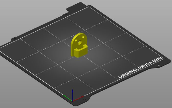
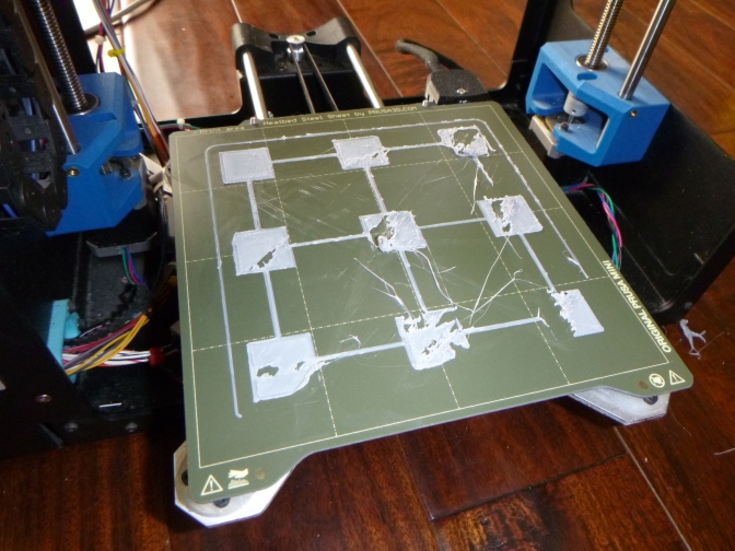
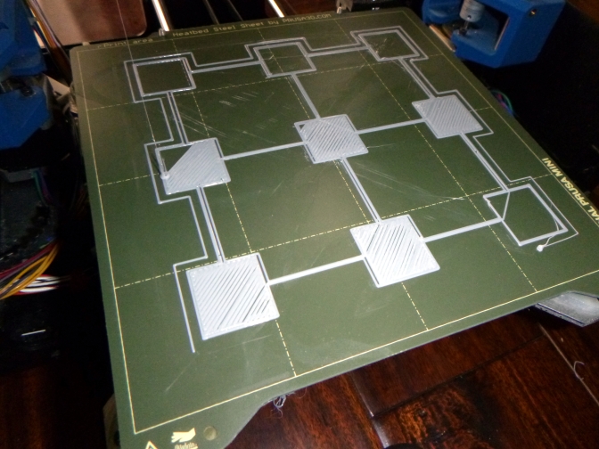
Anyway, back to the modification project. Things are going well. I have successfully test printed a few times. At first the prints were not centered on the bed, but I finally figured that out. I now am testing manual mesh bed leveling code in the marlin firmware and despite not having an automatic bed leveling probe it seems I can get this to work without one. I have not yet enabled memory saving so as of now i need to level the bed every time I use it, and this slows the whole process down a lot. I probably will enable that next so i can use octoprint again and just click “send print to printer”.

Eventually I want to replace the extruder assembly with one that has a pinda probe. I’m actually thinking I may want to use a Prusa MK3S printhead to keep things compatible with my other build. Not sure whether i will need to make other mods to accommodate that or not. I will at the very least need a cable adapter. If / when I do that I will most likely swap out the Rambo Mini for the Rambo Einsy (that i bought from Ultimaker) for the trinamic drivers and LCD support.

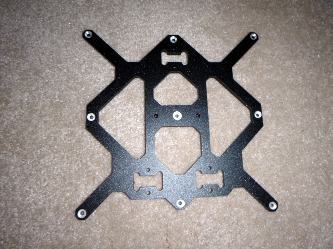
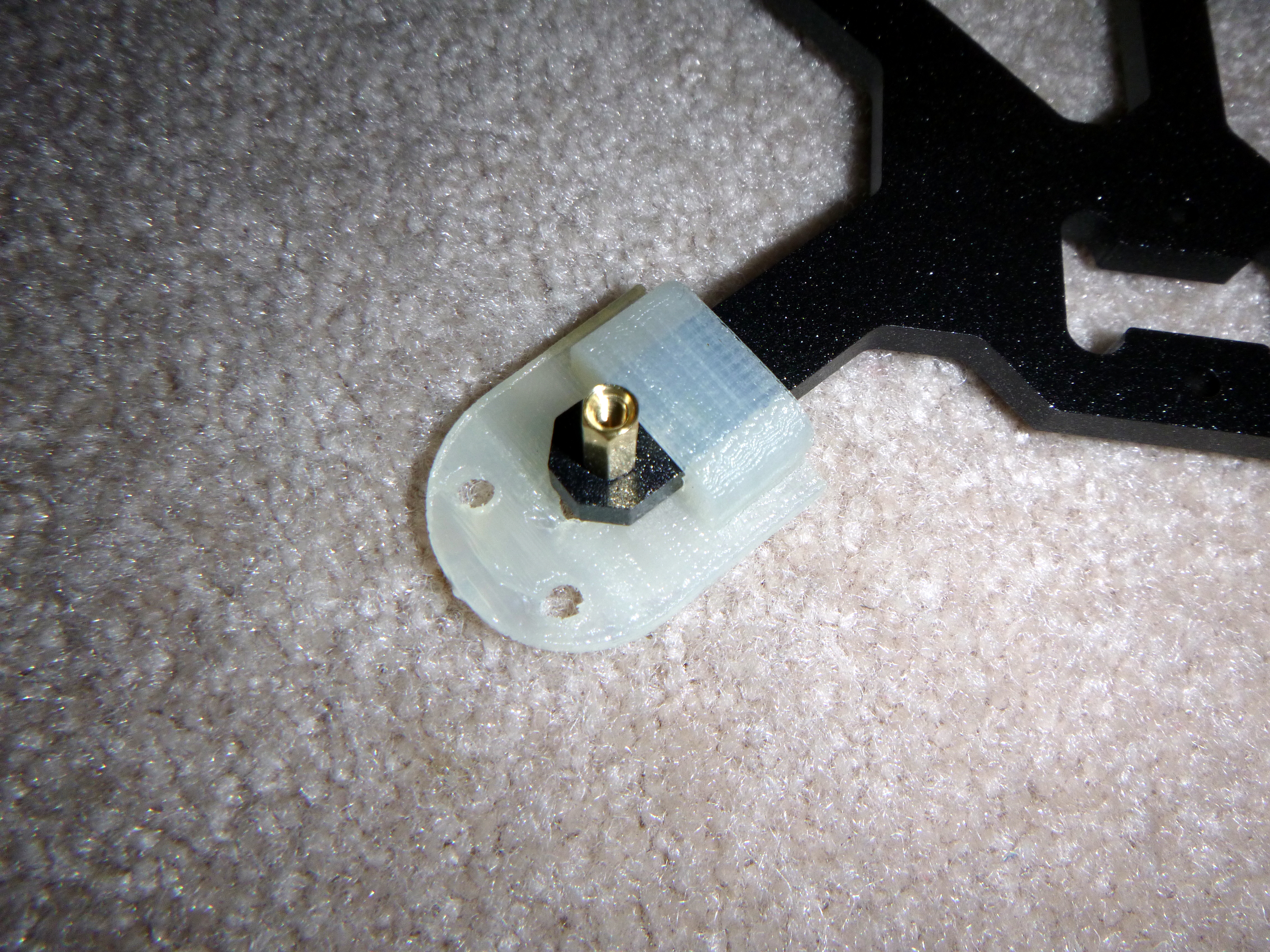
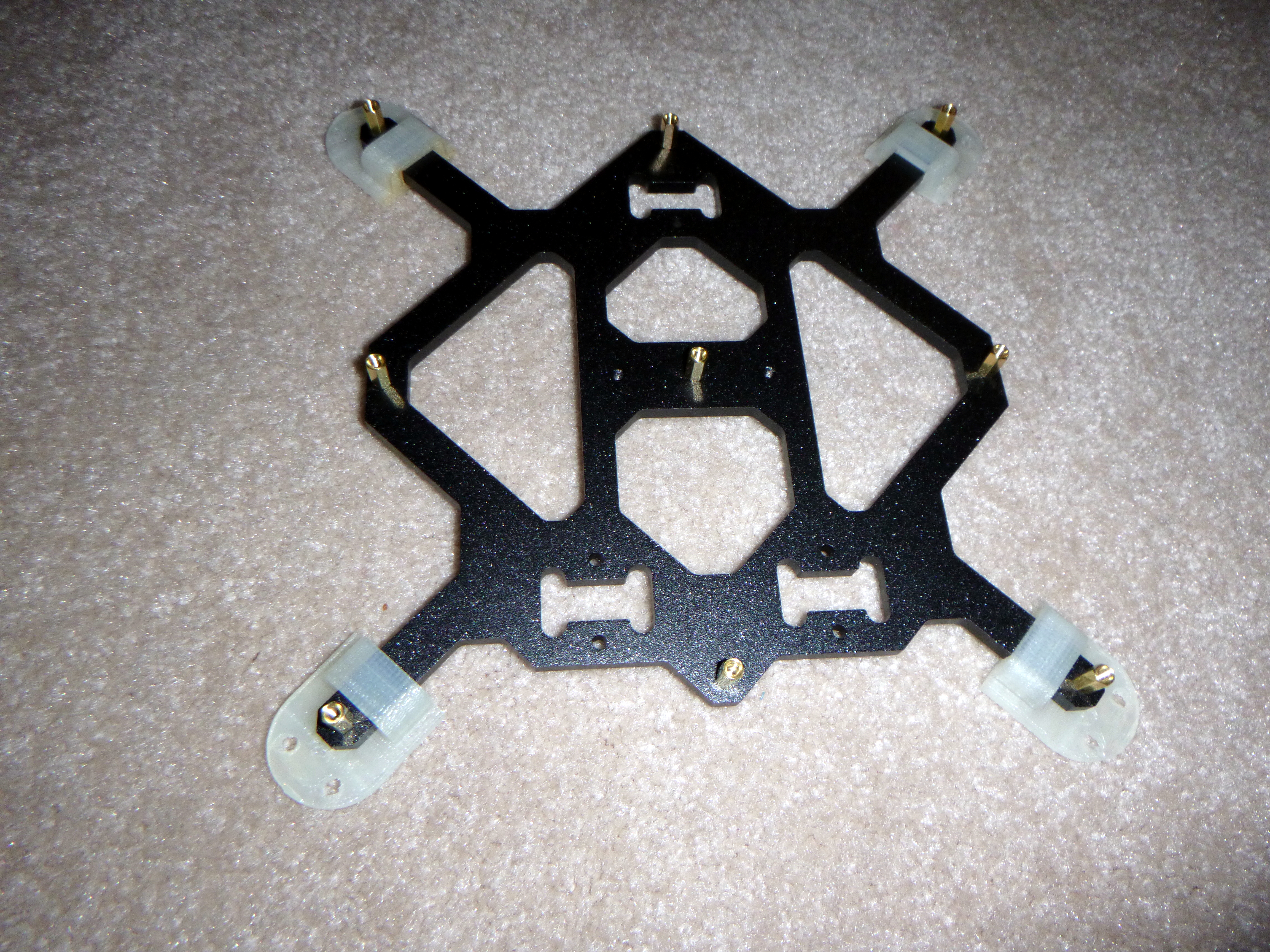
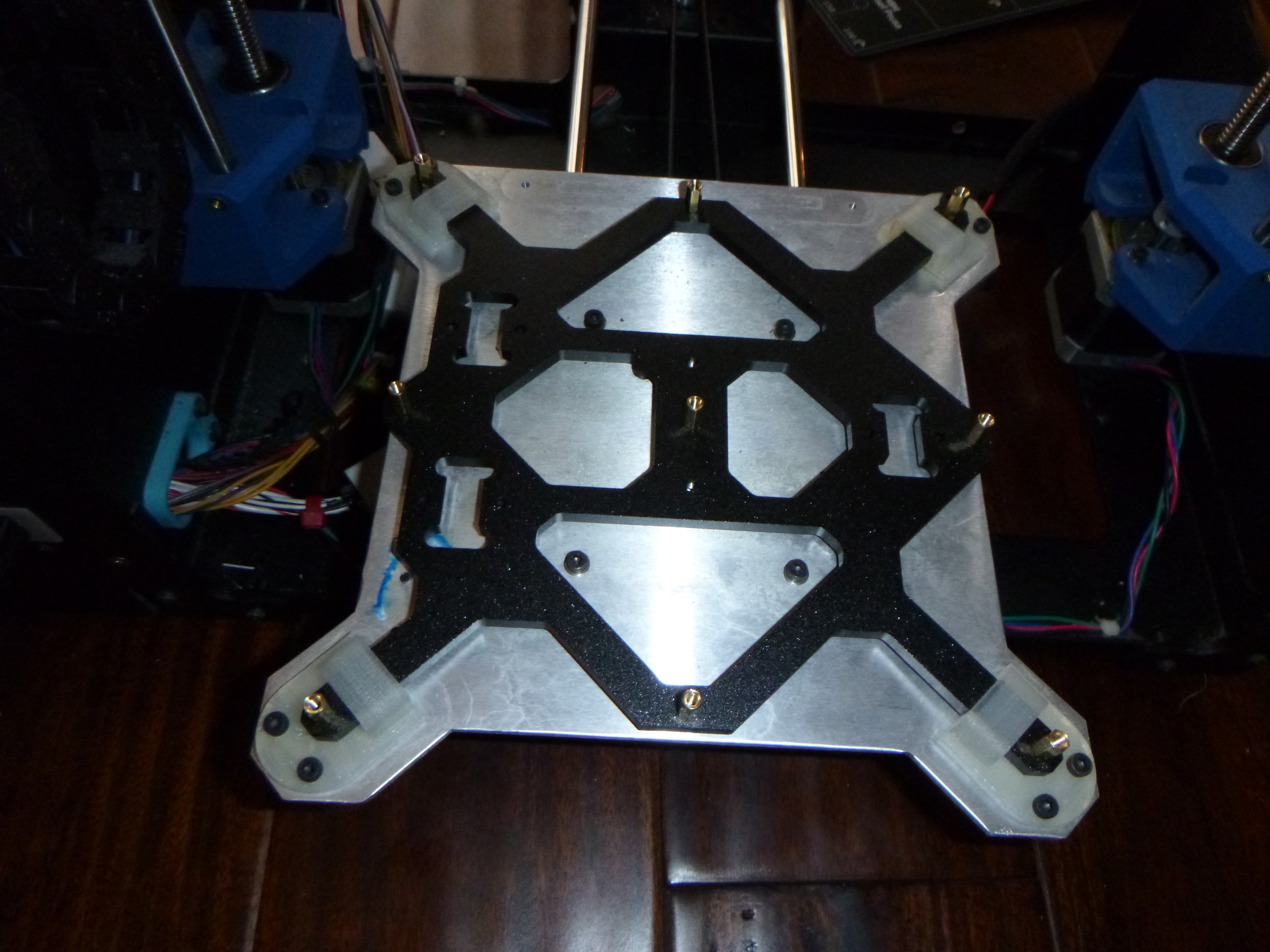
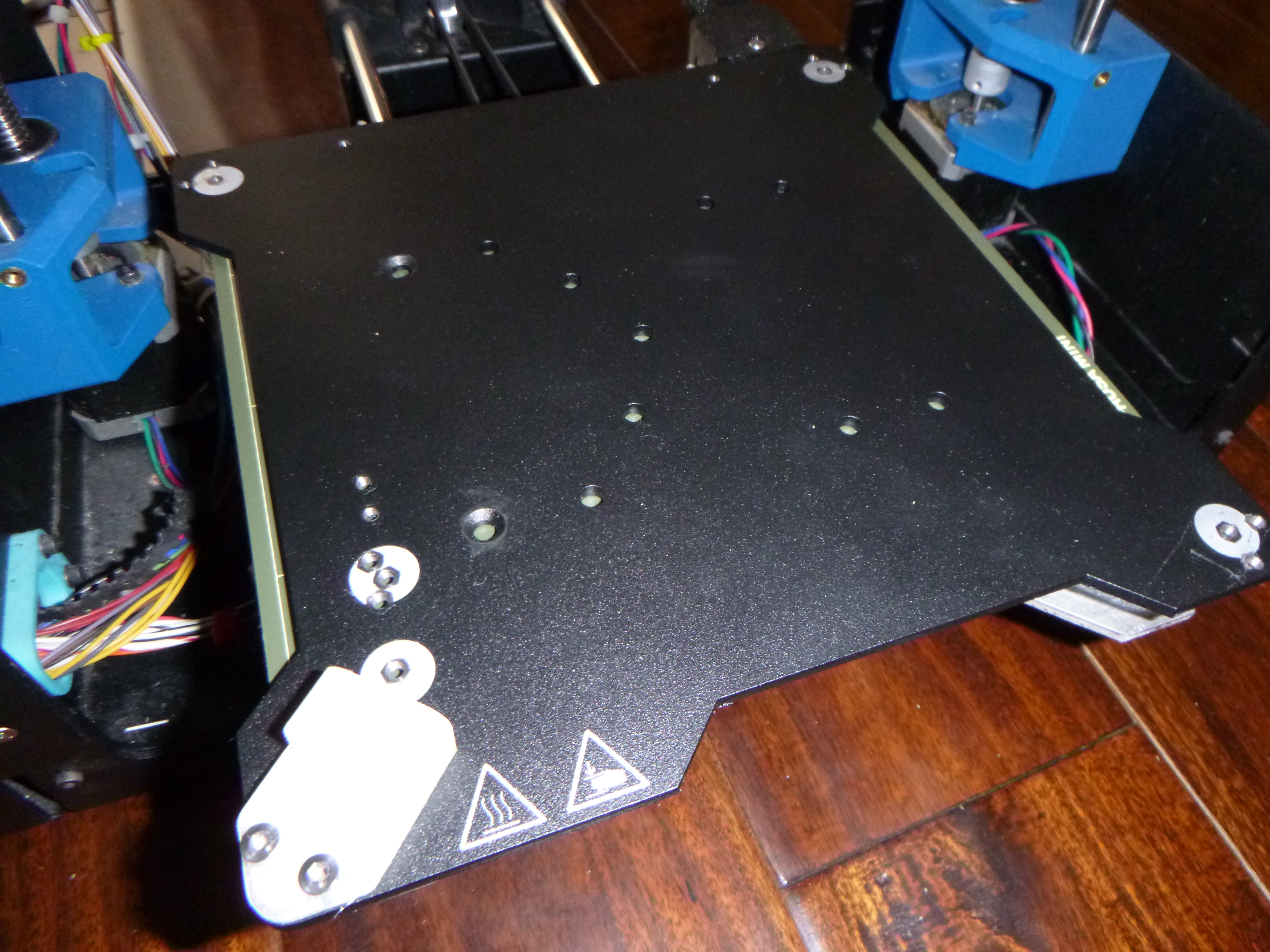
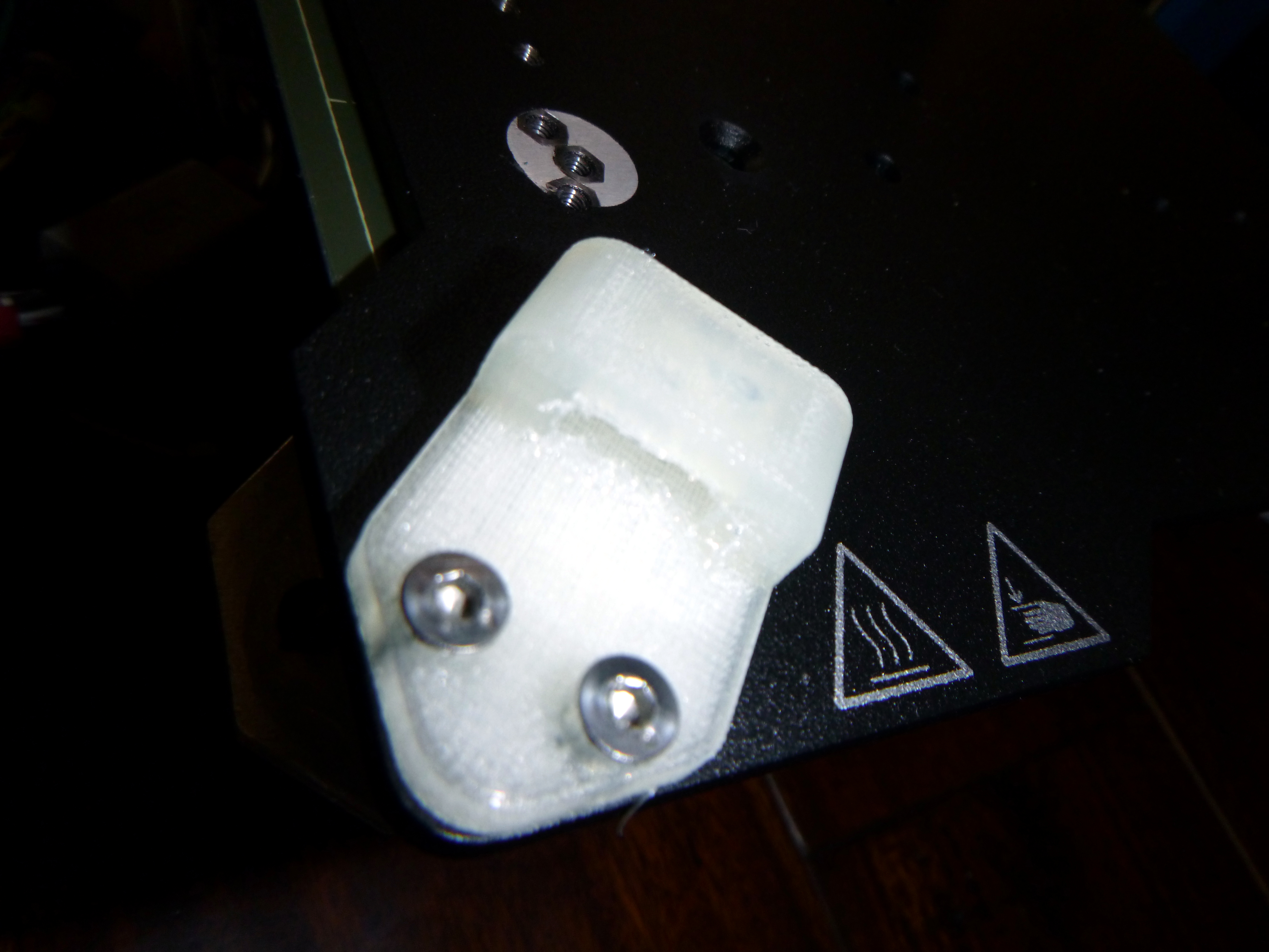
I came up with what I think is a pretty clever mounting system that still is fast, easy, and a complete drop-in replacement with no major modifications to either the prusa hardware or the lulzbot hardware. The only modifications needed were a small adapter for the heatbed cable and thermistor wires, and some countersunk holes on the bottom side of the prusa mini bed plate. The rest were 4 3D-printed ninjaflex corner mounts that hold things together quite well. I have posted the files on Thingiverse & soon to YouMagine.

https://www.thingiverse.com/thing:4604335

I am happy with how this mod has been turning out. I have tried to do it step by step with as few mini mods as possible so that it could perhaps be done by anyone, with any version of a Lulzbot Mini (1 or 2). I have tried not to stack the mods so that if one person wanted to repeat my process and only do just the bed replacement on a really old Lulzbot Mini 1 without changing the electronics or the extruder print head then that would work. On the other hand if someone wanted to do this on a Lulzbot Mini 2 or in combinations with other mods, those could probably work fine too. The firmware does need to be replaced regardless though as the bed height is higher than the old one and no bed leveling probe is currently installed so major z-axis crashing would occur.

I at least have a fairly up to date version of Marlin working decently well now. It uses the Drunken Octopus fork and is fairly up to date with Marlin 2.0 and other upstream changes. So in many ways this firmware is an upgrade to what was on my mini before I started and can only improve. I want to double check motor settings for speeds and feedrates to make sure I have things optimized as best I can. But otherwise it seems to be working well with a properly tuned slicer.

A bad print before manual mesh bed leveling was attempted.

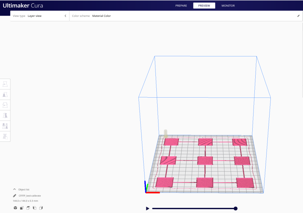
I have also officially abandoned the Lulzbot Cura 21.08 slicer. I was using the old Lulzbot Cura 21.08 instead of the newer Lulzbot Cura 2 because the older software just ran so quick compared to the new one and frankly I thought the new one sucked and looked like crap. I still do if i’m honest. But since I no longer have a stock Lulzbot machine anyway I figured I would give the newest version of the Ultimaker Cura a try. I was pleasantly surprised!

A better print after manual mesh bed leveling. I accidentally bumped the raspberry pi running octoprint, so that is why the print is only half finished.

Not only is the Ultimaker Cura more up to date and more polished than the Lulzbot fork, it comes in a better Linux package than the Lulzbot version that is not up to date with needed dependencies on my newer PopOS 20.04 laptop. So I literally could not even install the Lulzbot skinned version of Cura 2 on my Linux machine. Once I set up a custom printer in Ultimaker Cura I was pleased to find it worked great! It even made the motors twice as quiet! I tinkered around with trying to use PrusaSlicer to slice and control the lulzbot mini, but i have not figured out the best settings for the motors quite yet. I got it to work once, then it reverted to it’s default motor settings and sounded terrible. Since Ultimaker’s Cura worked flawlessly with no motor adjustments and the motors were so quiet compared to the old Lulzbot Cura 21.08 and PrusaSlicer (for now), I will be using Ultimaker’s Cura until I am ready to tinker with PrusaSlicer again.

Calling all Electronics Wizards and Open Source Hardware enthusiasts to help me fix my Motor Controller…

Okay. So, i’m a little embarrassed that this thing is still not working. I’ve made cool progress on it over the years, but not the part that matters… that it actually works. This should not be that hard. Since it’s basically an HIP4081A beefy full h-bridge controller and an Arduino it should not be all that complicated. I think what i need to do is just spend some money on known good components and true schottky diodes and mosfets and just breadboard this thing out. Once i can get this reliably working on a breadboard i can come back to the PCB design stuff. I know last time i messed with it i had a few PCB wiring issues and when i was testing the h-bridge i could only get one side to turn on. The other side was shorting out somehow.

20171123_111038

Having said that, i’m still pretty happy with the overall PCB design and direction that is heading. I really enjoy the two PCBs that plug into each other via male and female headers ans sockets. I just put up my files (in their old unkempt state) onto GitHub for version tracking and in true Open Source Hardware fashion for others to hopefully help collaborate with me on this. I really really really want to see this thing work someday and turn into a cool motor controller that people use all over to build cool robots and stuff with in the near future.

20171123_111058

So, please… If you are good with electronics and electronic theory, especially motor control, if you are an open source enthusiast, if your good with git, if you are good with EagleCAD, if you have an interest in a cool Open Source motor controller based on MOSFETS, if you were a user of the old FIRST Robotics, VEX Robotics, or IFI Victor 884s or 885s that this design is based on (now a defunct product to my knowledge), if you’d like a motor controller you can hack, use I2C or add a CAN bus or some other device such as a current sensing circuit, or who knows what else, then PLEASE PLEASE Help Me! Help me get this thing working and ready for market and usability and hackability. I’m not ashamed to ask for help or to admit that i need it. I’m proud of how far i got with as little electronics knowledge as i do have, but concede that there are so many other people out there that can help!


I have uploaded the last freeze of this project onto a new github project for you all to easily get the source files here: https://github.com/keen101/XYZZY-Motor-Controller

I’ve also designed a neat little 3d printable base to keep this thing from shorting out. And i will track down the other design files that are relevant or that this design is based on in the next couple days / weeks.

20171123_111133


*Bonus Offer: I have several old PCBs of V. 1.0 laying around. For anyone willing to help me with this project i would be willing to send you up to 3 copies of the top and the bottom boards each to play with (while supplies last). There are i think at least two potential PCB trace errors (that i can’t remember what at the moment) that are on the boards, but hey, free boards and it’s not that hard to cut a trace or two and rewire if needed. You would just need to obtain the needed mosfets, diodes, arduino, and HIP4081A h-bridge driver chip to work on the project. Heck, i’m even willing to entertain replaccing the HIP4081A chip to a different one if there are any better or cheaper options that do basically the same thing. Please Help 🙂

Preview: Upgraded Bread Machine Incubator TR444 [in progress…]

20171114_125852

Ok. So! Back to hardware / electronics projects!! Yay!

This is a preview for an upcoming post. I am currently working on upgrading my Hacked Breadman Breadmachine TR444 Incubator from a previous project. I’m adding some RGBW neopixel LEDS from Adafruit for light. It will have a button to change lighting sequences from White to red/blue to purple, to blue, to black. All the colors one would need to 1. see into the machine. 2. Color LEDs to grow seedlings for gardening. 3. blue which may come in handy for bacteria cultures? IDK. maybe not. But whatever. I currently have the arduino code for the light sequence working.

I will also be adding a fan for circulation. I 3D printed the fan holder. I may or may not have a button to control the fan. I will have a big red button to start the incubator cycle (37 Degrees C for bacteria / fungal petri dishes). And i am considering another button for a programmed Dry Heat Sterilization routine. As mentioned before, according to Wikipedia:

The proper time and temperature for dry heat sterilization is 160 °C (320 °F) for 2 hours or 170 °C (340 °F) for 1 hour.

I also think i will be integrating my Chronodot real-time clock for use with this dry heat sterilization routine and possibly some other incubating cycle as well. Cool! Fun stuff! Lets get working!!

p.s. post in the comments if these are the kind of projects you’d like to see more of of! 🙂

20171114_125921


Progress on my Homebuilt Lulzbot Mini

Today i made significant progress on building my own Lulzbot Mini 3D printer from scratch. Technically i now have two 3d printers i’m building from scratch, but the other one is bigger and one i’m designing myself. Just like me to not finish one project before starting another. At least i’m going to work on this one and finish it before continuing on my other one (which might be converted into a homemade CNC mill).

DSCF7351

Today was a major milestone because most of the components are put together and i finally was able to test part of the electronics i wired up myself. I was able to test the Y-axis motor and limit switches as well as the X-axis stepper motor. All seemed to function correctly using Lulzbot’s Cura software. The software did have an unexpected safety feature however, it wouldn’t let me turn any of the motors on without the bed thermistor wired up. So i had to wire up a temporary 10k thermistor for testing purposes. It worked great. I was running the Cura software under Ubuntu Linux. The Cura software gave me an error that it could not autodetect the serial port or something like that, so i ran it as the root super user and that fixed the problems.

DSCF7353.JPG

Since i’m building this thing from scratch instead of buying one premade i’m trying to find ways of cutting costs. Although i think i will end up spending more than i hoped. But anyway, part of that is looking into ways that i might be able to replace expensive commercial products like the IGUS bearings and the Leadscrew nut. I’ve already drafted up a 3d printable version of the leadscrew nut and posted it here on Thingiverse. The nut has yet to be tested, but i’ve also had some RJM-01-08 IGUS bearing replica prototypes made in Nylon. The RJM-01-08 IGUS replica bearings turned out to be too tight, but with a drill i was able to make them usable. They are currently being used to remove the wiggle and slop i was experiencing from using the 1mm too small LM8UU ball bearings.

delrin_nut_2_preview_featured

I originally got the LM8UU bearings as a cheaper alternative to the commercial RJM-01-08 IGUS stock bearings the Lulzbot mini uses thinking they would work. They work, and i am currently using some, but the stock STL files from Lulzbot have holes that are 1mm too big because of the slight size difference between them and the LM8UU. I might try to modify the STL files [i have modified the lulzbot solidworks files] to make LM8UU compatible parts in the near future, but for now i’m happy with my 3d printed nylon ones. I’ve heard PLA might work too, so i will experiment with that in the future as well.

DSCF7355.JPG

Here are some more pictures:

DSCF7347.JPG

DSCF7346.JPG

DSCF7314.JPG

Fixing Mesh Issues & Layer Gaps in 3D Printing

So today i had an interesting experience. As i have been lately, i sometimes go to the library to print out parts I’ve designed for my custom 3D printer project. While they print i use the time to crunch out upcoming essays for for school.

But this time instead of the printer happily moving along and producing perfect parts i got a rude awakening. The parts that came out looked like picture #3. Instead of my corner pieces being printed with two triangular pyramids and four “arms” they printed with one triangle, a “tail” and two “spaghetti blobs” on the side in a mess. It looked more like a deformed geometric fish instead.

Looking for info online i found helpful information on the Ultimaker Forum. It seems if i go into Layer view beforehand i can see what it will print out like and see any obvious gaps before hand. X-ray mode is even more helpful in a situation like this because if there are any faces or walls that have problems they get highlighted in bright red.

As you can see on mine, the bad models have several red triangular “internal” walls. The models have internal walls because they were created in Solidworks as assemblies from smaller parts and “digitally glued together”. Normally that shouldn’t cause a problem, but for some reason it did.

Currently i’m using Solidworks 2007 to create my 3D models. I wish i could use a good Open Source CAD program that works in Ubuntu Linux, but sadly none really exist. Not to my liking anyway. FreeCad has potential, but has a long way to go. OpenSCAD looks decent, but is for people who have mathematical minds. Sadly i don’t. And Blender has amazing graphics, but is not a CAD program. If someone could combine the beautiful elegance of Blender while stripping out it’s over-complexity and merging it with FreeCAD, and taking the user friendliness of Solidworks it would be perfect. Oh, and it has to be cross-platform (meaning runs on Ubuntu Linux). So until that day i’m forced to use a proprietary CAD program on a otherwise useless proprietary operating system, either on it’s own machine (or run in a virtual machine like Virtualbox). Far from an elegant solution. -End Of Rant. lol.

For me my problem was some sort of issue with the internal walls. Normally this should not be a problem. Since my version of Solidworks does not export whole assemblies as STL files (instead each separate part is exported into STL), I’ve been using 3dContentCentral to convert my CAD files into single STL files. Apparently the issue i ran into arises when i export my assemblies into single part files before converting them to STL. If i instead upload the entire assembly (and dependencies) and convert those to STL files it seems to work fine. Somehow that makes a difference when fixing whatever was wrong with those internal walls/faces. Whatever. At least i’m happy to find a solution.

I wanted to fix my bad CAD models from the beginning, but for example if i had a bad STL file that was not created by me and i still needed to print it, i could turn to Cura’s expert settings. In Cura’s expert settings there are some tools that attempt to “fix horrible” models that would otherwise fail to print correctly. I could have gone that route to print them anyway, but for me the better solution was to fix the source of the problem which was a bad CAD model.

cura_good_model2

So, all in all, check your parts before you print them. Cura’s x-ray mode and layer mode are invaluable tools that can help you avoid problems with your 3D printing endeavors.

This site also gives some good tips on bad edge geometry and bad STL meshes.

Updating and perfecting the XYZZY Motor Controller

XYZZY_Top_Board_V1.0

I’m working on finishing and perfecting an old project of mine (by a few years). The XYZZY Motor Controller (H-bridge). The old design was only somewhat functional. Enough to prove proof of concept (barely), but i want a sleek, finished version that people can actually use. So i’m working on perfecting this prototype design. I’ve just updated several things on the top board, and i think it’s done. The biggest issue was a pretty major design flaw which was that i forgot to add the safety diodes for motor kickback. In simple terms that meant that when the motor stopped turning or i switched it from forward to backward the electrical energy would destroy the Mosfets! …oh.. noo… Yup.

Not to worry, they are there now. I will be wiring them in manually to some of my old prototype boards to test soon. This design is progressed enough to update it to V1.0 instead of Rx.x number. Although the top board is finished, the bottom board needs quite a bit of work and possibly major redesigning. from the looks of my old design for the bottom board it looks like one feature i wanted to implement was an I2C bus. That would make it cool to connect them together and then to a microprocessor to monitor them in real-time. The only sensors to monitor at this point was the inclusion of a crude temp sensor and monitoring the RPM of the fan. Although i was hoping to build an arduino chip built in. When i eventually purchase new PCB’s i think this revision is finally deserving for the color red! Although purple or black would look pretty sick too. Any comments are welcome.

This is an Open Source Hardware Design.

DSCF7247 DSCF7248

DSCF7249

DIY Modified Bread Machine Incubator

I hereby present: “The Breadman Incubator”… TaDa!

I will admit that i never truly got into the DIYbio movement, but to say it didn’t leave an impact on me also wouldn’t be truthful. So what is this machine? And what is it for? Well, I’m glad you asked…

DSCF7140 DSCF7145

In short this is a modified bread machine. Only modified to the extent that the native electronics have been replaced with an arduino (in this case an old low-cost diavolino), an arduino screw-shield, the native thermistor replaced with my own 10k ntc thermistor, and a 7 segment display from sparkfun electronics. Oh, and my own custom orange plexiglass cover! I’m quite proud of that cover! It’s main design is to regulate specific temperatures. In the case of DIYbio, in theory it can be used to regulate a temperature to be an incubator. Mainly bacteria, but it could also be used as an egg incubator, or a “hyper germination chamber” for squash seeds!. This last one is the only one i have actually tested, and i was able to see a squash seedling emerge in only one day! All of these potential uses still fall within the category of do-it-yourself biology.

DSCF7146 DSCF7151

Currently the programming is limited to a pre-set temperature at 37 degrees Celsius. This is often the optimal temperature to cultivate bacteria. Or so i’m told by Wikipedia. It is also the max temperature listed as being able to germinate squash seeds. huh, who knew?

DSCF7155 DSCF7156

Now, a lot of people out there might say: “why on earth would you want to cultivate bacteria!” and one step further: “why on earth would you make a machine to grow bacteria!; Isn’t that dangerous?!” Well, umm.. I never said i actually would grow bacteria in this thing, more i created it just because i like the “i could” factor. In reality this is more of a proof-of-concept design built only to impress myself. But to answer the second question/statement.. Yes, growing bacteria is potentially dangerous.. unless you know what you are doing, what kind of bacteria is safe to work with, and proper safety protocols. Those who are familiar with the DIYbio movement will know that such safety concerns have been discussed before and that the general consensus is basically “use common sense” and “know what you are doing”. If these two principles are followed everything will be fine.

Besides, the great thing about this is that in theory this could be programmed to be it’s own sterilizer too! That’s a great plus for safety. Wikipedia say’s this:

Eventually, the entire item reaches the proper temperature needed to achieve sterilization. The proper time and temperature for Dry-Heat sterilization is 160 °C (320 °F) for 2 hours. Instruments should be dry before sterilization since water will interfere with the process. Dry-heat destroys microorganisms by causing coagulation of proteins.

I did a basic programming test to see if this machine could reach 160 degrees Celsius. It seemed like it could. The only thing needed would be a way to accurately keep track of time (like the unused chronodot i have lying around) and a button or something to initiate a programmed sterilization routine.

DSCF7157 DSCF7158

In this design i have not implemented use of the motor. One because i really couldn’t think of a good use for it. But two because in my initial testing phase i accidentally destroyed both an arduino mega and my computer (i assume by not properly protecting them from the kickback electricity from the motor). Yeah, it was “my bad”! Quite literally. Yeah, so a caution to anyone who decided to build a similar project, i recommend not programming your arduino while it is plugged into the electronics of your bread machine. Program it first, and then hook it up to test it. It was only when the usb cable of my arduino were plugged into my computer (with the motor running (i think)) that bad things happened. 😦

DSCF7159 DSCF7161

I found this old piece of scrap aluminum that handily fits at the bottom to cover the motor thingy. It gives it a nice flat surface. Petri dishes or anything that needs a flat surface will need something like this.

So.. Does it work?.. Yup. At least in a basic sense. It definitely could use some improvement. The programming is very basic in terms of turning the relay on if it is under a preset temperature (in this case 37°C) and turning it off it is above. While this works, it is not efficient nor really all that accurate. A PID loop would probably improve it much. Also adding a chronodot would help to have a temperature compensated accurate time clock in case i wanted to incubate something for a specific amount of time. I probably will add the chronodot at some point. A fan to help regulate temperature might also be a good fix, but if the autoclave feature were implemented it would have to be autoclavable (or removable). The fan could unintentionally introduce mold spores, but if proper sterilizing techniques were used this could be avoided. And perhaps a magnet switch to turn things off when the cover is opened.

bread_machine_pinout

The arduino code for this project can be found here.