Calling all Electronics Wizards and Open Source Hardware enthusiasts to help me fix my Motor Controller…

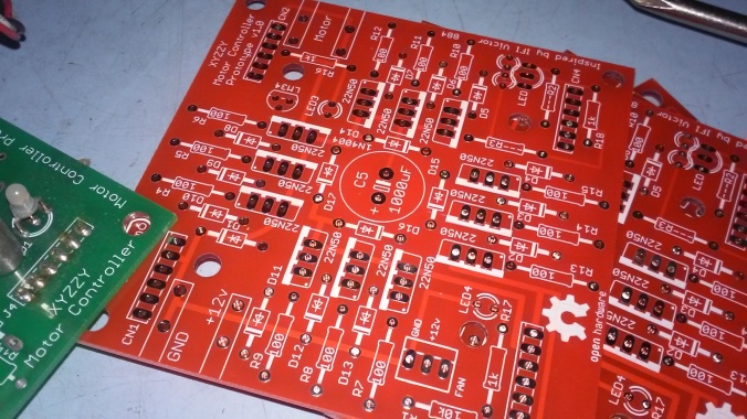
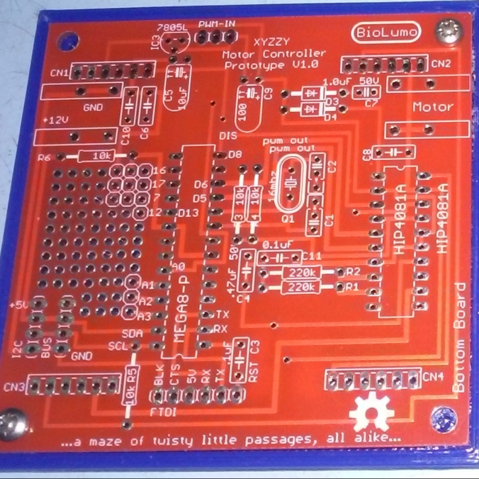
Okay. So, i’m a little embarrassed that this thing is still not working. I’ve made cool progress on it over the years, but not the part that matters… that it actually works. This should not be that hard. Since it’s basically an HIP4081A beefy full h-bridge controller and an Arduino it should not be all that complicated. I think what i need to do is just spend some money on known good components and true schottky diodes and mosfets and just breadboard this thing out. Once i can get this reliably working on a breadboard i can come back to the PCB design stuff. I know last time i messed with it i had a few PCB wiring issues and when i was testing the h-bridge i could only get one side to turn on. The other side was shorting out somehow.

20171123_111038

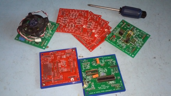
Having said that, i’m still pretty happy with the overall PCB design and direction that is heading. I really enjoy the two PCBs that plug into each other via male and female headers ans sockets. I just put up my files (in their old unkempt state) onto GitHub for version tracking and in true Open Source Hardware fashion for others to hopefully help collaborate with me on this. I really really really want to see this thing work someday and turn into a cool motor controller that people use all over to build cool robots and stuff with in the near future.

20171123_111058

So, please… If you are good with electronics and electronic theory, especially motor control, if you are an open source enthusiast, if your good with git, if you are good with EagleCAD, if you have an interest in a cool Open Source motor controller based on MOSFETS, if you were a user of the old FIRST Robotics, VEX Robotics, or IFI Victor 884s or 885s that this design is based on (now a defunct product to my knowledge), if you’d like a motor controller you can hack, use I2C or add a CAN bus or some other device such as a current sensing circuit, or who knows what else, then PLEASE PLEASE Help Me! Help me get this thing working and ready for market and usability and hackability. I’m not ashamed to ask for help or to admit that i need it. I’m proud of how far i got with as little electronics knowledge as i do have, but concede that there are so many other people out there that can help!


I have uploaded the last freeze of this project onto a new github project for you all to easily get the source files here: https://github.com/keen101/XYZZY-Motor-Controller

I’ve also designed a neat little 3d printable base to keep this thing from shorting out. And i will track down the other design files that are relevant or that this design is based on in the next couple days / weeks.

20171123_111133


*Bonus Offer: I have several old PCBs of V. 1.0 laying around. For anyone willing to help me with this project i would be willing to send you up to 3 copies of the top and the bottom boards each to play with (while supplies last). There are i think at least two potential PCB trace errors (that i can’t remember what at the moment) that are on the boards, but hey, free boards and it’s not that hard to cut a trace or two and rewire if needed. You would just need to obtain the needed mosfets, diodes, arduino, and HIP4081A h-bridge driver chip to work on the project. Heck, i’m even willing to entertain replaccing the HIP4081A chip to a different one if there are any better or cheaper options that do basically the same thing. Please Help 🙂

Preview: Upgraded Bread Machine Incubator TR444 [in progress…]

20171114_125852

Ok. So! Back to hardware / electronics projects!! Yay!

This is a preview for an upcoming post. I am currently working on upgrading my Hacked Breadman Breadmachine TR444 Incubator from a previous project. I’m adding some RGBW neopixel LEDS from Adafruit for light. It will have a button to change lighting sequences from White to red/blue to purple, to blue, to black. All the colors one would need to 1. see into the machine. 2. Color LEDs to grow seedlings for gardening. 3. blue which may come in handy for bacteria cultures? IDK. maybe not. But whatever. I currently have the arduino code for the light sequence working.

I will also be adding a fan for circulation. I 3D printed the fan holder. I may or may not have a button to control the fan. I will have a big red button to start the incubator cycle (37 Degrees C for bacteria / fungal petri dishes). And i am considering another button for a programmed Dry Heat Sterilization routine. As mentioned before, according to Wikipedia:

The proper time and temperature for dry heat sterilization is 160 °C (320 °F) for 2 hours or 170 °C (340 °F) for 1 hour.

I also think i will be integrating my Chronodot real-time clock for use with this dry heat sterilization routine and possibly some other incubating cycle as well. Cool! Fun stuff! Lets get working!!

p.s. post in the comments if these are the kind of projects you’d like to see more of of! 🙂

20171114_125921


Bitten by the Electronics Bug

So recently I’ve been bitten by the project bug again. And quite a bit by electronics hobby-type stuff again in particular, though not exclusively. More blog posts and updates to come soon.

dscf8030

On the left is my old homemade DIY arduino based avr high voltage programmer made on old Hewlett Packard Engineering Protoboard based off of Jeff’s original design that i made in 2011. On the right is my brand new updated model named the AVR HV Rescue Shield 2 from MightyOhm.com. It’s main function is to help reset the fuses on AVR chips when you program them wrong. My old one came in handy and has saved a few chips from time to time. The new one obviously is better, mostly because now that i’m tinkering more with attiny85V chips i now have a High Voltage Rescue shield for them too, though it also does not require an external 12VDC power source as it has some sort of built in surface mount step up voltage chip.

dscf8031

So as briefly mentioned above i’ve been tinkering with trying to program attiny85v AVR chips. I’ve dug out my old trusty USBtinyISP AVR Programmer and I’ve recently gotten a Sparkfun Tiny AVR Programmer.

What i’m really intending to do is make a shrunk down version of my old Mystery Project by re-purposing and reprogramming my Adafruit TV-b-gone kit. I just need to get the frequency right. I’m starting by seeing if i can compile and upload the tvbgone AVR/arduino code to a blank attiny85 first. If i can do that i can work on changing the code. So far though i haven’t gotten the AVR fuses correct yet to use the tvbgone’s external 8mhz oscillator, though i think the program has uploaded correctly. That’s why i needed the HV Rescue Shield 2 mentioned above.

In addition, i finally ordered the parts to finish my DIY Arduino MENTA boards. They are cool Adafruit designed Arduino compatible boards that fit into an Altoids mint tin.

dscf8032

Some of the other items I’ve been tinkering with have been Raspberry Pi’s, including various Linux-based Operating Systems including Raspian (a debian based distro), Octopi (debian running Octoprint – 3D printer software), and RetroPie (an emulator to play old roms for NES, SNES, Playstation, Atari, Gameboy, and other popular gaming systems). The tiny $5 Raspberry Pi Zero. Tinkering with automatic plant lights and a gardening moisture sensor. And my fancy new SparkFun Vernier Interface Shield an upgrade to interface my Vernier sensors with Arduino. More on that in another post soon!

dscf8033

I also recently ordered a USB cable in order to salvage a scrounged barcode scanner that my brother saved from the Barnes And Noble dumpster. The USB cable works! Now i just need to figure out a use for it. Not bad for a $10 cable on ebay to a functional $200 value barcode scanner.

1st test of repstrap reprap stepper motor


I have three small (tiny really) stepper motors in my “junk box”. I eventually want to build some cool CNC machines. RepRap, CNC router, CNC mill, CNC lathe. Okay, but to get there i need to learn more about this technology. Best way for me to learn is by doing through experimentation. I have to start small, so i will be attempting to build a repstrap “starter” machine. Today i used a sparkfun easy driver to drive a stepper. It was awesome. It was similar to the first tutorial, and the 2nd video mixed together.

http://vimeo.com/3978871

here is the arduino sketch so far. (version 1)

////////////////////////////////////////////////////////
// Stepper Motor skecth for use with the EasyDriver 4.2
////////////////////////////////////////////////////////

// Original by Dan Thompson 2008
//
// Musical test version 1 by Andrew Barney
//
// Use this code at your own risk.
// For all the product details visit http://greta.dhs.org/EasyDriver/
// For the full tutorial visit http://danthompsonsblog.blogspot.com/
//

int dirpin = 3;
int steppin = 12;

void setup() {
Serial.begin(9600);

pinMode(dirpin, OUTPUT);
pinMode(steppin, OUTPUT);
}
void loop()
{

int i;

Serial.println(“>>”);
for (i = 0; i<4000; i++) // Iterate for 4000 microsteps.
{
digitalWrite(steppin, LOW); // This LOW to HIGH change is what creates the
digitalWrite(steppin, HIGH); // “Rising Edge” so the easydriver knows to when to step.
delayMicroseconds(200); // This delay time is close to top speed for this
} // particular motor. Any faster the motor stalls.

Serial.println(“<<“);
for (i = 0; i<4000; i++) // Iterate for 4000 microsteps
{
digitalWrite(steppin, LOW); // This LOW to HIGH change is what creates the
digitalWrite(steppin, HIGH); // “Rising Edge” so the easydriver knows to when to step.
delayMicroseconds(300); // This delay time is close to top speed for this
} // particular motor. Any faster the motor stalls.

Serial.println(“<<“);
for (i = 0; i<4000; i++) // Iterate for 4000 microsteps
{
digitalWrite(steppin, LOW); // This LOW to HIGH change is what creates the
digitalWrite(steppin, HIGH); // “Rising Edge” so the easydriver knows to when to step.
delayMicroseconds(400); // This delay time is close to top speed for this
} // particular motor. Any faster the motor stalls.

Serial.println(“<<“);
for (i = 0; i<4000; i++) // Iterate for 4000 microsteps
{
digitalWrite(steppin, LOW); // This LOW to HIGH change is what creates the
digitalWrite(steppin, HIGH); // “Rising Edge” so the easydriver knows to when to step.
delayMicroseconds(500); // This delay time is close to top speed for this
} // particular motor. Any faster the motor stalls.

Serial.println(“<<“);
for (i = 0; i<4000; i++) // Iterate for 4000 microsteps
{
digitalWrite(steppin, LOW); // This LOW to HIGH change is what creates the
digitalWrite(steppin, HIGH); // “Rising Edge” so the easydriver knows to when to step.
delayMicroseconds(600); // This delay time is close to top speed for this
} // particular motor. Any faster the motor stalls.

Serial.println(“<<“);
for (i = 0; i<4000; i++) // Iterate for 4000 microsteps
{
digitalWrite(steppin, LOW); // This LOW to HIGH change is what creates the
digitalWrite(steppin, HIGH); // “Rising Edge” so the easydriver knows to when to step.
delayMicroseconds(700); // This delay time is close to top speed for this
} // particular motor. Any faster the motor stalls.

Serial.println(“<<“);
for (i = 0; i<4000; i++) // Iterate for 4000 microsteps
{
digitalWrite(steppin, LOW); // This LOW to HIGH change is what creates the
digitalWrite(steppin, HIGH); // “Rising Edge” so the easydriver knows to when to step.
delayMicroseconds(800); // This delay time is close to top speed for this
} // particular motor. Any faster the motor stalls.

delay(1000);

}