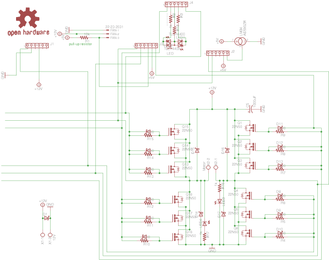
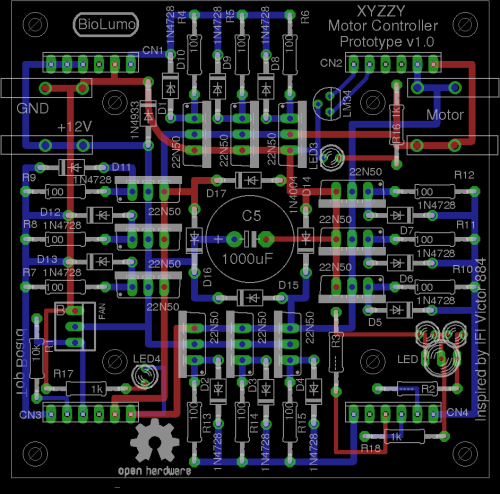
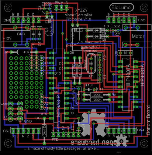
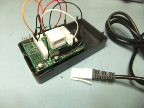
Calling all Electronics Wizards and Open Source Hardware enthusiasts to help me fix my Motor Controller…

Okay. So, i’m a little embarrassed that this thing is still not working. I’ve made cool progress on it over the years, but not the part that matters… that it actually works. This should not be that hard. Since it’s basically an HIP4081A beefy full h-bridge controller and an Arduino it should not be all that complicated. I think what i need to do is just spend some money on known good components and true schottky diodes and mosfets and just breadboard this thing out. Once i can get this reliably working on a breadboard i can come back to the PCB design stuff. I know last time i messed with it i had a few PCB wiring issues and when i was testing the h-bridge i could only get one side to turn on. The other side was shorting out somehow.
20171123_111038

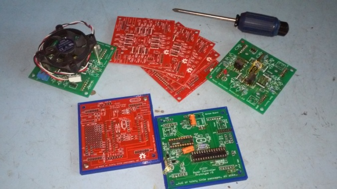
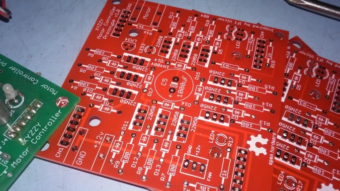
Having said that, i’m still pretty happy with the overall PCB design and direction that is heading. I really enjoy the two PCBs that plug into each other via male and female headers ans sockets. I just put up my files (in their old unkempt state) onto GitHub for version tracking and in true Open Source Hardware fashion for others to hopefully help collaborate with me on this. I really really really want to see this thing work someday and turn into a cool motor controller that people use all over to build cool robots and stuff with in the near future.
20171123_111058

So, please… If you are good with electronics and electronic theory, especially motor control, if you are an open source enthusiast, if your good with git, if you are good with EagleCAD, if you have an interest in a cool Open Source motor controller based on MOSFETS, if you were a user of the old FIRST Robotics, VEX Robotics, or IFI Victor 884s or 885s that this design is based on (now a defunct product to my knowledge), if you’d like a motor controller you can hack, use I2C or add a CAN bus or some other device such as a current sensing circuit, or who knows what else, then PLEASE PLEASE Help Me! Help me get this thing working and ready for market and usability and hackability. I’m not ashamed to ask for help or to admit that i need it. I’m proud of how far i got with as little electronics knowledge as i do have, but concede that there are so many other people out there that can help!


I have uploaded the last freeze of this project onto a new github project for you all to easily get the source files here: https://github.com/keen101/XYZZY-Motor-Controller

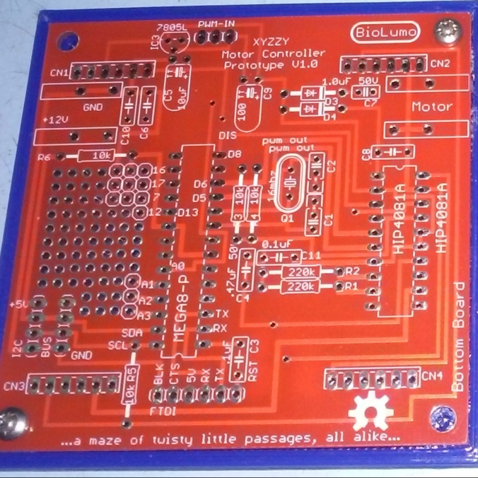
I’ve also designed a neat little 3d printable base to keep this thing from shorting out. And i will track down the other design files that are relevant or that this design is based on in the next couple days / weeks.
20171123_111133


*Bonus Offer: I have several old PCBs of V. 1.0 laying around. For anyone willing to help me with this project i would be willing to send you up to 3 copies of the top and the bottom boards each to play with (while supplies last). There are i think at least two potential PCB trace errors (that i can’t remember what at the moment) that are on the boards, but hey, free boards and it’s not that hard to cut a trace or two and rewire if needed. You would just need to obtain the needed mosfets, diodes, arduino, and HIP4081A h-bridge driver chip to work on the project. Heck, i’m even willing to entertain replaccing the HIP4081A chip to a different one if there are any better or cheaper options that do basically the same thing. Please Help 🙂

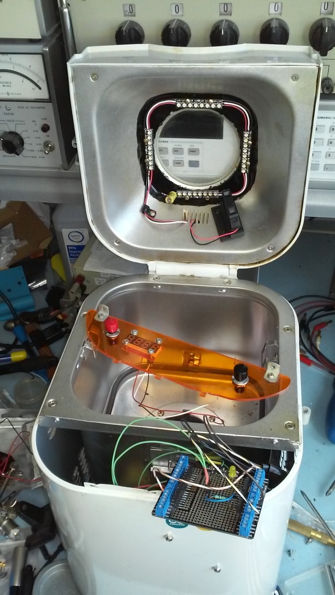
Preview: Upgraded Bread Machine Incubator TR444 [in progress…]

20171114_125852

Ok. So! Back to hardware / electronics projects!! Yay!

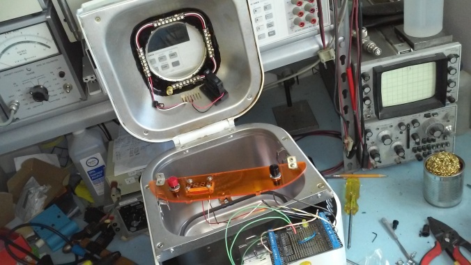
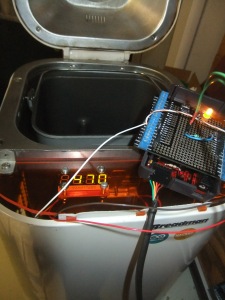
This is a preview for an upcoming post. I am currently working on upgrading my Hacked Breadman Breadmachine TR444 Incubator from a previous project. I’m adding some RGBW neopixel LEDS from Adafruit for light. It will have a button to change lighting sequences from White to red/blue to purple, to blue, to black. All the colors one would need to 1. see into the machine. 2. Color LEDs to grow seedlings for gardening. 3. blue which may come in handy for bacteria cultures? IDK. maybe not. But whatever. I currently have the arduino code for the light sequence working.

I will also be adding a fan for circulation. I 3D printed the fan holder. I may or may not have a button to control the fan. I will have a big red button to start the incubator cycle (37 Degrees C for bacteria / fungal petri dishes). And i am considering another button for a programmed Dry Heat Sterilization routine. As mentioned before, according to Wikipedia:

The proper time and temperature for dry heat sterilization is 160 °C (320 °F) for 2 hours or 170 °C (340 °F) for 1 hour.

I also think i will be integrating my Chronodot real-time clock for use with this dry heat sterilization routine and possibly some other incubating cycle as well. Cool! Fun stuff! Lets get working!!

p.s. post in the comments if these are the kind of projects you’d like to see more of of! 🙂

20171114_125921


Continuing Progress on the XYZZY Motor Controller

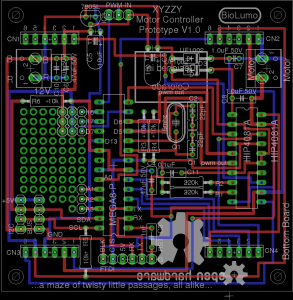
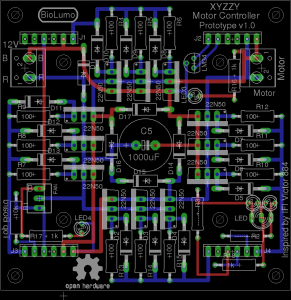
bottom_board_v1.0top_board_v1.0

I think i’ve finished the design for the XYZZY Motor Controller, which for me is a big statement. I embarrassingly probably even said it before too. But anyway both the top board and the bottom board are done in Eagle Cad and i think i’m satisfied. The top board relatively stayed the same since it’s design was fairly sound. All that was needed was a few safety diodes for the mosfets, some led’s, and some minor resistors which were not critical. The bottom board was another story however.

It required a complete redesign except for the basic underlying parts. Many of the items i had on the board were just potential “goodies” that were extraneous and non-critical, so i removed them. Not only did it help remove extra unrouted wires, it helped clear up some much needed room. In the end i ended up with some extra room that i turned into a tiny proto board area that i’m quite pleased with. Along the way i fixed a few errors on the schematic and routed things nicer than they were before. I think all that it needs now is to order up some PCB’s and do some more testing and programming.

The only things i would like to change are the screw terminals. The ones that are on the schematic now are much too small for a large amp motor. The problem is i can’t seem to find an Eagle Cad footprint for one. I may have to end up creating my own part in eagle cad eventually. If you know of one please let me know in the comments below! I’m looking for something like these: photo1, photo2, photo3.

The XYZZY Motor Controller is a modular open source hardware mosfet speed controller h-bridge. It has been designed to be able to handle high current motors with the parallel mosfet design. It has been designed to be hackable and DIY accessible (hence the all through hole design). It has been designed for flexibility. Since it has been created with the hope in mind of a built-in arduino brain it can be easily programmed for many things. I’ve routed one PWM capable I/O port to function as a PWM directional input (modeled after the IFI Victor 884 servo input design). But one feature i’m happy to include is an easily accessible I2C port. This port gives the motor controller many potential abilities. One idea is to use the I2C port to expand it’s capabilities (such as a current sensor), or i think it would be cool to use I2C to daisy-chain several motor controllers together to help save wiring and to provide real-time feedback to a master microprocessor or computer. Another cool “feature” is that possible boards could be fixed with half the parts. If for example the mosfets died for some reason, but the bottom components were fine (or vice versa) you could use the good parts with other good parts. Since my old top board is basically the same i plan to test it with a new bottom board sometime in the near future. I expect it to work fine.

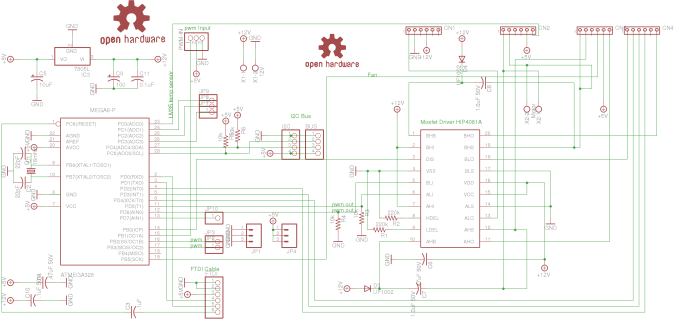
The schematics are somewhat rough. I’ve tried to clean them up as best i can. But don’t expect them to be pretty. The reason one schematic has floating wires going nowhere on one side is that at one point these were part of one schematic. To create the two board system with the pluggable pin headers i had to split them into “two projects” at one point in time.

bottom_sch_v1.0 top_sch_v1.0

If you would like a copy of the current Eagle Cad files please let me know. This is an Open Source Hardware Design. I would love to see these in the wild or even improved versions of it. Perhaps someone with surface mount experience can create one with smaller parts. More prototype testing to come soon, i hope! 🙂

Update (9-15-15): I’ve updated it again only slightly. I’ve changed the resistors to have bigger pads using the adafruit eagle cad library parts, and instead of screw terminals i’ve decided to use spade connectors or quick disconnects. These make it less cumbersome to disconnect motors and power and no loosing of screws, but also saves space (which was more critical). I couldn’t find a library that had a spade connector already, i had to make it myself. It actually wasn’t too hard.

top_board_v1.0 bottom_board_v1.0

DIY Modified Bread Machine Incubator

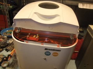
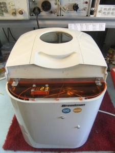
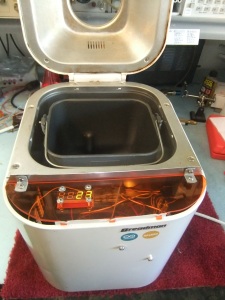
I hereby present: “The Breadman Incubator”… TaDa!

I will admit that i never truly got into the DIYbio movement, but to say it didn’t leave an impact on me also wouldn’t be truthful. So what is this machine? And what is it for? Well, I’m glad you asked…

DSCF7140 DSCF7145

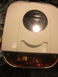
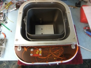
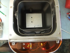
In short this is a modified bread machine. Only modified to the extent that the native electronics have been replaced with an arduino (in this case an old low-cost diavolino), an arduino screw-shield, the native thermistor replaced with my own 10k ntc thermistor, and a 7 segment display from sparkfun electronics. Oh, and my own custom orange plexiglass cover! I’m quite proud of that cover! It’s main design is to regulate specific temperatures. In the case of DIYbio, in theory it can be used to regulate a temperature to be an incubator. Mainly bacteria, but it could also be used as an egg incubator, or a “hyper germination chamber” for squash seeds!. This last one is the only one i have actually tested, and i was able to see a squash seedling emerge in only one day! All of these potential uses still fall within the category of do-it-yourself biology.

DSCF7146 DSCF7151

Currently the programming is limited to a pre-set temperature at 37 degrees Celsius. This is often the optimal temperature to cultivate bacteria. Or so i’m told by Wikipedia. It is also the max temperature listed as being able to germinate squash seeds. huh, who knew?

DSCF7155 DSCF7156

Now, a lot of people out there might say: “why on earth would you want to cultivate bacteria!” and one step further: “why on earth would you make a machine to grow bacteria!; Isn’t that dangerous?!” Well, umm.. I never said i actually would grow bacteria in this thing, more i created it just because i like the “i could” factor. In reality this is more of a proof-of-concept design built only to impress myself. But to answer the second question/statement.. Yes, growing bacteria is potentially dangerous.. unless you know what you are doing, what kind of bacteria is safe to work with, and proper safety protocols. Those who are familiar with the DIYbio movement will know that such safety concerns have been discussed before and that the general consensus is basically “use common sense” and “know what you are doing”. If these two principles are followed everything will be fine.

Besides, the great thing about this is that in theory this could be programmed to be it’s own sterilizer too! That’s a great plus for safety. Wikipedia say’s this:

Eventually, the entire item reaches the proper temperature needed to achieve sterilization. The proper time and temperature for Dry-Heat sterilization is 160 Â°C (320 Â°F) for 2 hours. Instruments should be dry before sterilization since water will interfere with the process. Dry-heat destroys microorganisms by causing coagulation of proteins.

I did a basic programming test to see if this machine could reach 160 degrees Celsius. It seemed like it could. The only thing needed would be a way to accurately keep track of time (like the unused chronodot i have lying around) and a button or something to initiate a programmed sterilization routine.

DSCF7157 DSCF7158

In this design i have not implemented use of the motor. One because i really couldn’t think of a good use for it. But two because in my initial testing phase i accidentally destroyed both an arduino mega and my computer (i assume by not properly protecting them from the kickback electricity from the motor). Yeah, it was “my bad”! Quite literally. Yeah, so a caution to anyone who decided to build a similar project, i recommend not programming your arduino while it is plugged into the electronics of your bread machine. Program it first, and then hook it up to test it. It was only when the usb cable of my arduino were plugged into my computer (with the motor running (i think)) that bad things happened. 😦

DSCF7159 DSCF7161

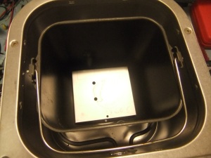
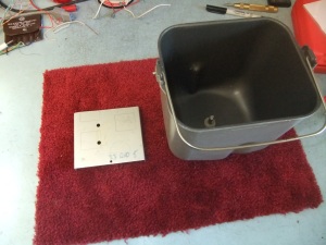
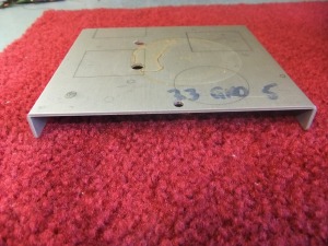
I found this old piece of scrap aluminum that handily fits at the bottom to cover the motor thingy. It gives it a nice flat surface. Petri dishes or anything that needs a flat surface will need something like this.

So.. Does it work?.. Yup. At least in a basic sense. It definitely could use some improvement. The programming is very basic in terms of turning the relay on if it is under a preset temperature (in this case 37°C) and turning it off it is above. While this works, it is not efficient nor really all that accurate. A PID loop would probably improve it much. Also adding a chronodot would help to have a temperature compensated accurate time clock in case i wanted to incubate something for a specific amount of time. I probably will add the chronodot at some point. A fan to help regulate temperature might also be a good fix, but if the autoclave feature were implemented it would have to be autoclavable (or removable). The fan could unintentionally introduce mold spores, but if proper sterilizing techniques were used this could be avoided. And perhaps a magnet switch to turn things off when the cover is opened.

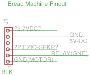
bread_machine_pinout

The arduino code for this project can be found here.

Breadman Incubator Arduino Code

The following arduino code is for my Modified Bread Machine Incubator project. The display code was not written by me, but was the only example code i was able to cobble together with my working thermistor and relay code that actually worked. I understand a little of it, but not all of it. If someone knows a better way to transmit the temperature from the thermistor to the 7 segment display, then i welcome improvements. Otherwise enjoy. 🙂

//* Working Code for modified bread machine incubator w/ safety code
//By Andrew Barney
//Loveland, Colorado, USA
//#DIYBIO
//Test code for Display and thermistor
//seems to work...

#include <math.h>
double Temp;
int RelayHOT = 9; //Caution: Heater on Pin 9!
int led = 13; //Led on pin 13

//display code starts here
#define TXDATA  8       // Pin used to transmit data.
#define POT     0       // pin used to read the analog value.
//int potVal=0;
int potVal=Temp;
#define BITTIME 93      // adjusted to obtain 104 milliseconds delay (9600bauds).
//display code ends here

double Thermistor(int RawADC) {
Temp = log(((10240000/RawADC) - 10000));
Temp = 1 / (0.001129148 + (0.000234125 + (0.0000000876741 * Temp * Temp ))* Temp );
Temp = Temp - 273.15;            // Convert Kelvin to Celsius
return Temp;
}

void setup() {
Serial.begin(9600); // begin the serial monitor
pinMode(RelayHOT, OUTPUT); //set pin 9 (known as relayHOT - to an output)
pinMode(led, OUTPUT); //Led on pin 13 to correlate when relayHOT is ON!

//display code continued here
 pinMode(TXDATA, OUTPUT);   // initialize the TXDATA pin as an output.
 digitalWrite(TXDATA,HIGH); // TXDATA = 5V when is resting.
 //delay(10);                 //Wait for Serial Display startup.
 sendChar('v');             //Reset the display 0x76.
//display code ends here 
 
 delay(500);  // Delay a bit… (both for display and safe start-up)
}

//display code
void sendChar(char c){
  delayMicroseconds(BITTIME*2);          // wait 2 Stop bits before sending the char
  digitalWrite(TXDATA,LOW);              // low the line
  delayMicroseconds(BITTIME);            // wait Start bit
  for (int i=0; i<8;i++){
    digitalWrite(TXDATA,bitRead(c, i));  // bit out.
    delayMicroseconds(BITTIME);          // wait bit
  }
   digitalWrite(TXDATA,HIGH);            //Return TXDATA pin to "1".
}

//-------------------------------------------------------------------------
void show(String s){
  for(int i=0;i<4;i++){
    sendChar(s[i]);
  }
}
//display code ends

void loop() {
//delay(500); // Delay a bit…
int(Thermistor(analogRead(0)));
//Serial.println(analogRead(A0)); // print the raw analog values (diagnostic purposes only)
//Serial.println(int(Thermistor(analogRead(0))));  // print Celsius temp reading in serial monitor
Serial.println(Temp);
delay(1000);  // wait 1 seconds before sampling temperature again

if (Temp < 37)
{digitalWrite(RelayHOT, HIGH);  //if the temperature is less than 37C, turn on the relay
digitalWrite(led, HIGH);}       //LED indicator

else if (Temp > 37)
{digitalWrite(RelayHOT, LOW);  //if the temperature is greater than 37C, turn the Heater off because it is too hot!
digitalWrite(led, LOW);}

//else if (Temp == 0)
//{digitalWrite(RelayHOT, LOW);  //turn the Heater off!
//digitalWrite(led, LOW);}

//else if (Temp == NAN)
//{digitalWrite(RelayHOT, LOW);  //turn the Heater off!
//digitalWrite(led, LOW);}

else if (analogRead(0) == LOW)  //check if thermistor is plugged in
{digitalWrite(RelayHOT, LOW);  //if it isn't turn the Heater off!
digitalWrite(led, LOW);}

//display code
//potVal= analogRead(0);
//potVal = Thermistor(analogRead(0));
potVal = Temp;
  String strPot = String (potVal);
  while(strPot.length()<4)strPot= " " + strPot;   //format to 4 characters.
  show(strPot);
  //delay(100);  
//display code ends

}

Interfacing Vernier Sensors and Arduino (and vice-versa!)

So, recently I’ve been bored. That’s nothing new really. The up side to the times when i get really bored is that i usually end up starting some sort of electronics project. Since i have an interest in the DIYBIO movement and an interest in DIY chemistry i have realized that it’s really cool (and helpful) when you can use sensors to collect your data. But up until now i haven’t had the motivation (or the money) to really dive into it. But today’s post may be the beginning to turning that tide.

Awhile back i stumbled across this post by David Hay, after noticing this question on adafruit. In it he tinkers a bit with interfacing an older vernier (light?) sensor with an arduino clone.  Since i use vernier sensors in my chemistry classes at school i have come to love them. I wondered if i could do something similar, but what i really wondered was whether i could do the opposite as well. Could i interface other non-vernier sensors (like sparkfun sensors) using an arduino to the fancy LoggerPro software or my TI84+ calculator? It turns i can!

DSCF15033

The LoggerPro software is really good stuff, but i’m cheap whenever i can be. That’s one reason i thought of my TI84+ calculator. I already have one of those, and vernier has released free software for it that can graph data from vernier sensors in real time. The program is called EasyData and can be downloaded here. The second option is to use LoggerPro on Linux. And since i’m already a full time Ubuntu user i get to use the newly updated free LoggerPro beta for Linux! Sweet Beans!

DSCF15011

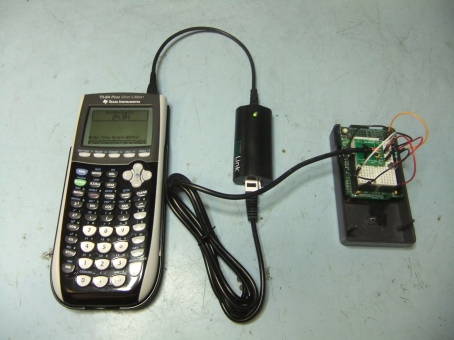
I’ve already tested both. They both work great. The cool thing is that i was able to hook an arduino to my calculator EasyData program and also LoggerPro on the computer by using a Vernier EasyLink (with an adapter to convert it into a GoLink). I had to get a Vernier Analog Breadboard Cable for it to work, but it was well worth it. I sent some test pwm values using the Arduino example code for the fading led on arduino digital port 9. I used the example pdf from the DIY Light Intensity Sensor example project on the Vernier website to help me out a bit.

DSCF15022

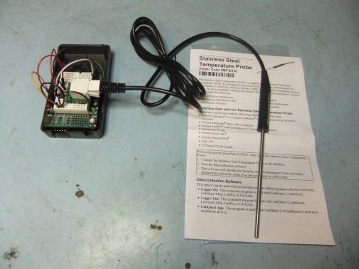
I was also able to do the opposite like what David Hay did with his sensor. I was able to successfully interface a stainless steel temperature probe from Vernier (which is basically just a thermister in a nice case) to my Arduino. I used the example pdf from the DIY Build a Temperature Sensor example project to help me out, along with the values in an equation provided in the manual that came with my stainless steel temp sensor. I also bought this nice Analog Proto Board Connector from vernier which allowed me to do this so quickly. Here is the code i used on my Arduino to calculate the temperature from this thermister.

*/
int led = 13;

#include <math.h>

#define ThermistorPIN 0 // Analog Pin 0

float vcc = 4.91; // only used for display purposes, if used
// set to the measured Vcc.
float pad = 15000; // balance/pad resistor value, set this to
// the measured resistance of your pad resistor
float thermr = 20000; // thermistor nominal resistance

float Thermistor(int RawADC) {
long Resistance;
float Temp; // Dual-Purpose variable to save space.

Resistance=((1000 * pad / RawADC) – pad);
Temp = log(Resistance); // Saving the Log(resistance) so not to calculate it 4 times later
Temp = 1 / (0.001129148 + (0.000234125 * Temp) + (0.0000000876741 * Temp * Temp * Temp));
Temp = Temp – 273.15; // Convert Kelvin to Celsius
Temp = Temp / 2;

// BEGIN- Remove these lines for the function not to display anything
//Serial.print(“ADC: “);
//Serial.print(RawADC);
//Serial.print(“/1024”); // Print out RAW ADC Number
//Serial.print(“, vcc: “);
//Serial.print(vcc,2);
//Serial.print(“, pad: “);
//Serial.print(pad/1000,3);
//Serial.print(” Kohms, Volts: “);
//Serial.print(((RawADC*vcc)/1024.0),3);
//Serial.print(“, Resistance: “);
//Serial.print(Resistance);
//Serial.print(” ohms, “);
// END- Remove these lines for the function not to display anything

// Uncomment this line for the function to return Fahrenheit instead.
//temp = (Temp * 9.0)/ 5.0 + 32.0; // Convert to Fahrenheit
return Temp; // Return the Temperature
}

void setup() {
Serial.begin(9600);
pinMode(led, OUTPUT);
}

void loop() {
float temp;
temp=Thermistor(analogRead(ThermistorPIN)); // read ADC and convert it to Celsius
Serial.print(“Celsius: “);
Serial.print(temp,1); // display Celsius
//temp = (temp * 9.0)/ 5.0 + 32.0; // converts to Fahrenheit
//Serial.print(“, Fahrenheit: “);
//Serial.print(temp,1); // display Fahrenheit
Serial.println(“”);
digitalWrite(led, LOW);
delay(1000); // Delay a bit…
digitalWrite(led, HIGH);
}

So what does this mean? I think this opens up a whole new world of possibilities. On the one hand i believe i can now use the nice Vernier LoggerPro or EasyData real-time graphing software to interface non-vernier sensors like Arduino boards directly and perhaps others like a Sparkfun Alcohol sensor? (which i have one i would like to try) This should make it easy to interface cheap sensors in chemistry and biology labs that already have vernier equipment. I think it also means that we can now easily use Vernier sensors on non-proprietary devices such as cheap Arduino micro-controllers.

I also look forward to soon tinkering with using an Arduino webserver as a different real-time sensor graphing and data logging device. I hope in the future i can help to create other tools which might be useful for DIYBIO and other DIY science.

Hydra CNC mill

So, I’ve wanted a reprap for a while now. I’ve wanted a CNC router/mill for even longer. But, the reprap seems overkill maybe, and what i really want is a machine that could do both. *cue fancy music here*  TADA! I give you the Hydra-MMM CNC machine.

Okay, So I’m thinking about building one. It certainly is a nice looking machine. And it runs on an Arduino Mega. And the software is open source, and looks as good any professional gcode software i’ve ever used. And here’s the kicker… It has multi-headed tool support… which basically means you could have a RepRap plastic extruder on one, and a mill bit on the other. Or maybe a small mill bit on one, and a larger bit on the other.

I’m just thinking about it for now, but i will be sure to add more posts if i decide to build one.

http://objects.reprap.org/wiki/Hydra-MMM_Prototype

http://cpwebste.blogspot.com/

more XYZZY motor controller pictures

In honor of the most popular post on my blog in 2010, I’ve decided to upload a few more pictures of the XYZZY motor controller prototype. This time they were taken in high resolution with my new digital camera.

I still haven’t done anything new with it. And technically it’s still unfinished. But, i consider it a partial success anyway. Well, Enjoy.

XYZZY Motor Controller Prototype

http://s1010.beta.photobucket.com/user/keen101/library/electronics

p.s. here is a nice short article that describes the basics about H-bridges. I especially like the part at the end when it talks about the brake mode. Very useful feature on large robots or even an electric tractor. Here.

Successful XYZZY motor controller prototype

I have good news today! I got my R9 prototype boards the other day, and today successfully assembled and tested it today. I used whatever random parts io could find, and it still works!! I had to test with external arduino. 3. the fan mounting holes were slightly off, but they were close enough that i could still mount the fan. 5. I had a half bad HIP4081A chip. But, fortunately i had 3 “extra”. 6. to get it to turn in one direction or the other each HIP4081A input must be grounded, so my arduino PWM code was “backwards”, so to speak…

BUT, IT WORKED!!!!!! I used general diodes for the charge pump circuit, random capacitors for the power regulation, 22N50 mosfets that i got (about 100) in an Electronic Goldmine surprise box. Those surprise boxes were well worth it just for the mosfets!!!! This revision works instead of shorting out, since i fixed the p-channel mixup earlier, which is a relief. It felt good to finally finish this project. get a somewhat working prototype. It’s technically not finished, but it’s oh so close. Just needs a little redesigning, an opamp, and someone to program code for it.

I hope this homemade speed controller can help cut costs for FIRST Robotics students (on personal robots), so they dont have to buy expensive speed controllers for summer projects, or other hobbyists in autonomous robot competitions. I estimate that you can buy the boards for about ~$60, and the parts for ~20 without scrounging. But, you usually get 2 copies from batchpcb, so the “real price” is about $50 which is at least half the price of the IFI/VEX controllers.

The design could use a few little improvements. I’m still annoyed at the tiny solder pads that eagle cad produces, it’s hard to solder on the boards. http://forums.adafruit.com/viewtopic.php?f=25&t=13885

Edit #2: /more-xyzzy-motor-controller-pictures/

XYZZY Motor Controller is born…

haha, okay. so I’m pretty confident that my open source speed controller design is pretty much finished. Maybe some minor tweaks in the future, but otherwise pretty good. Of course I could have made some huge electronics mistake when i was designing it, but i dont know for sure. I guess i will just have to test it out, and figure out how to program the arduino code for it.

Too bad i didn’t finish adding reverse voltage protection, or a current sensing. Although i did add an I2C port, so a current sensing circuit could be added on later i suppose….

XYZZY Motor Controller - Top Board

XYZZY Motor Controller - Bottom Board

anyway, yeah. Just a Eagle CAD design right now, but i hope soon i will actually have a real one in my hands to tinker with. It would be even cooler if someone like SparkFun Electronics used my design to make a commercial version. I think it would do well with the annual sparkfun autonomous vehicle competition’s they hold. here is the forum to follow any new progress…

EDIT: …The design is supposed to use N-channel mosfets… but…in eagle cad i thought i used an N-channel (it even it said it was), but it turns out it was a P-channel. So, my prototype v.0.1 or whatever doesn’t work at all. Anyway.. i fixed it now. https://keen101.wordpress.com/2010/03/06/xyzzy-design-flaw-grrrr/

Edit #2: /successful-xyzzy-motor-controller-prototype/